Pile Driving Analysis (PDA) from instrumentation
Pile Driving Analysis (PDA) is the name of a specific set of instruments and calculations used to measure wave transmission through a pile as it’s driven and estimate its capacity. Generally, PDA is performed on only a small percentage of piles in a given project because it’s expensive to perform and slows down the construction (because of the instrument installation). PDA data contains measurements of strain and acceleration signals that can be used to calculate the force and speed of pressure waves traveling through the pile. This data can be interpreted to determine an estimate of the pile’s capacity, the maximum tension and compression stresses in the pile, and detect whether the pile has been damaged.
The PDA instrumentation enhancement will use data from one or more blows at the end of driving to produce a capacity estimate to compare to the estimate from a pile-driving log. Additionally, the pile stresses and damage indications (if any) will be reported and compared to the material strength as a quality control check on the pile’s structural integrity. A mathematical framework for the combustion model will is described below.
The focus of this option is quality control and capacity verification.
PDA instruments
The image below shows a typical PDA instrument setup on a steel pipe pile.
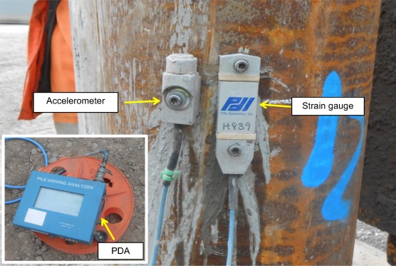
The data collected during pile-driving is evaluated in detail on an individual blow basis. It’s common to evaluate one or two blows per pile for the analysis, with one of the analyzed blows always representing the condition at the end of driving. Fundamentally, PDA analysis involves interpreting the signals as compression and tension waves traveling down (and back up) the pile from the hammer impact.
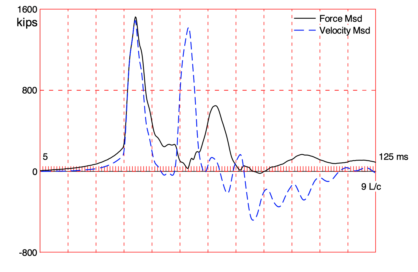
The figure below shows PDA data from a single blow on a pile. Although the instruments measure strain and acceleration, they are usually converted into force and velocity, respectively. Beneath the figure is a video of a simulation of the wave traveling through the pile after a hammer blow.
The Case Method for pile capacity
The Case Method is a closed-form solution based on a few simplifying assumptions such as ideal plastic soil behavior and an ideally elastic and uniform pile. Given the measured pile top force, \(F(t)\), and pile top velocity, \(v(t)\), the total soil resistance is:
\[R_{tot}(t) = \frac{1}{2} \left(F(t) + F(t_2) + Z\left[v(t)-v(t_2)\right]\right)\]
where
\(t =\) a point in time after impact
\(t_2 =\) time \(t + 2L/c\)
\(L =\) pile length below instruments
\(c = \sqrt{E/\rho}\) is the speed of the stress wave
\(\rho =\) pile mass density
\(Z = E A / c\) is the pile impedance
\(E = \rho c^2\) is the pile elastic modulus
\(A =\) pile cross sectional area
The total soil resistance consists of a dynamic (\(R_d\)) and a static (\(R_s\)) component. The static component is therefore:
\[R_s(t) = R_{tot}(t) - R_d(t)\]
It is this static soil resistance we use to characterize the pile capacity for design. The dynamic component of soil resistance is not used because when the pile is used to support a structure, the loads are generally applied so slowly that the dynamic soil resistance is negligible.
The dynamic component may be computed from a soil damping factor, J. Using wave considerations, this approach leads to the dynamic resistance:
\[ R_d(t) = J \left[F(t) + Z v(t) - R_{tot}(t)\right]\]
You may assume a damping factor of \(J = 0.5\) (a common value for sandy soil) for your project. Most commonly, \(t\) is set to that time at which the static resistance becomes maximum.
Static soil resistance sources
The static soil resistance is often broken down into “friction” and “end bearing”. The frictional resistance comes from the soil’s interaction with the sides of the pile. The end bearing comes from the soil’s interaction with the pile tip.
Because the wave speed of the pile is known, the time it takes for the wave to return to the instruments from the pile tip can be calculated (\(2L/c\)). Any wave energy (and therefore any soil resistance) detected by the sensors before this time cannot have returned from the pile time. So the frictional resistance of the soil is taken as the static resistance at \(t = 2L/c\) from the start of the impact wave.
Pile set
The pile “set” is the amount of permanent displacement resulting from a single blow. The signal from the velocity signal can be integrated to estimate the displacement:
\[ d(t) = \int v(t) dt\]
The displacement at the end of the recorded data is the pile set.
Comparing models
The models described above allow us to estimate the pile capacity and the pile set. These same parameters can be estimated from the pile-driving log.
In this project option, groups will compare the PDA-based estimates for capacity and pile set to the log-based estimates for one or two pile blows. The PDA-based capacity estimates will be plotted (as points) on the log-based pile capacity figures.